COMPONENTS - SIMPLY EXPLAINED
|
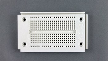
BreadboardThis is the base for prototyping and testing circuits.
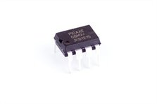
Follow this link to learn more about how breadboards work. Picaxe Microcontroller ChipThis is the 'brain' and controls the inputs and outputs through its legs (digital pins).
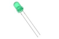
LED (Light Emitting Diode)LED lights are polarised which means they only allow electric current to flow in one direction.
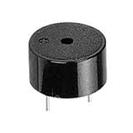
They have a positive leg (anode) and a negative leg (cathode). The positive leg is the longer leg on an LED. BuzzerThis is the speaker device used to transmit sound. It is not polarised so it does not have negative and positive legs.
|
|
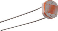
Light Dependent Resistor (LDR)This detects changes in light levels and can be used as an input device.
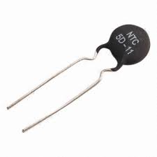
ThermistorThis is a sensor which measures temperature and is an input device.
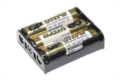
Battery PackThe battery pack holds 3 x 1.5V batteries which equates to 4.5V.
The Picaxe will run on a minimum of 3V. |
